Disclaimer: If it matters, I am not charging anyone to fix or diagnose this panel. It will be fixed but the exercise is mainly for fun and education.
I know it has at least one major safety problem and several smaller “you should do it another way” kind of problems. Interested in what others think about it.
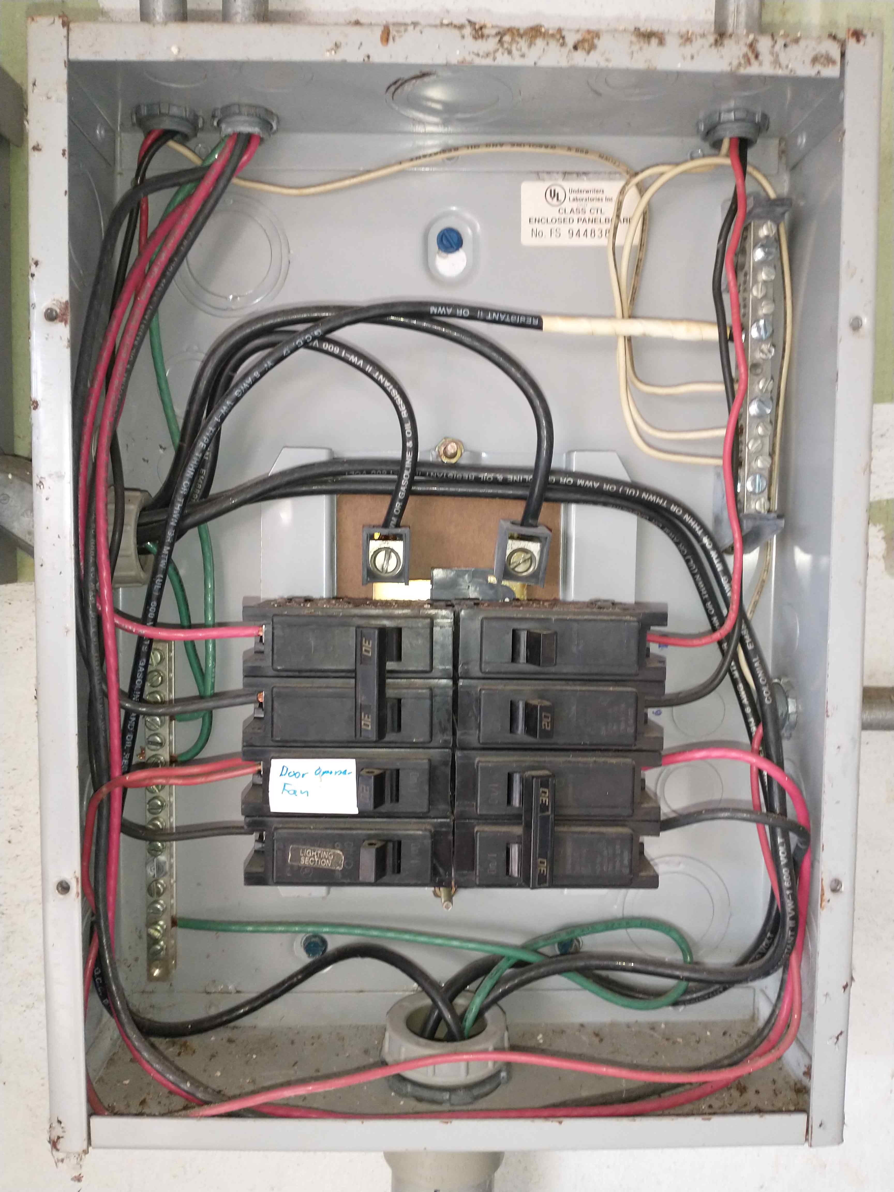
Here’s what I think is wrong with it:
The main thing I see is that the brand of circuit breakers are Challenger which are considered a fire hazard. This brand is no longer used and must be replaced for safety. As far as I’m aware they’re considered to be responsible for thousands of house fires. At least insurance companies would say so. In all fairness the label is pretty hard to see in these photos.
Things that I would think are less major:
The feeder lines look like they’re over-torqued & the lugs are bent. The key is not filled out and it covers part of the manufacturing label. I am not seeing a double groove on these breakers at the connection so it makes me think the double tapped breaker is not rated for that. The box is rusted up which could indicate moisture problem.
Things that don’t seem like a problem to me but someone may know better:
Someone has routed the feeder lines up through the knockout to a switch box on the left, then back into the box we are considering. Not sure if it’s against code or anything but it looks amateurish. There is a taped 6 gauge grounded conductor going to the neutral bus that is but I think that’s acceptable.
These are the problems I found. Click the blurred text to revile my answers:
Lack of breaker labels.
Double-tapped breaker.
This subpanel should have four conductors to isolate grounds and neutrals. (I’m not 100% sure on this one, the panel does have four conductors, but two come from a different knockout than the others…)
8 AWG wire is only rated for 50 amps - subpanels should be 100 amp.
Grounding bar is not bonded to the subpanel enclosure.
Wire sheaths are trimmed a little too much (this is another I’m not 100% sure on…).
the way the disconnect is done is questionable, also it’s labelled main while it appears the feeder comes through the bottom conduit then goes into the disconnect and comes back to feed the panel. 300.20?
I have a question, the panel to the left has a “Main” label but because the main disconnect is not actually in the right panel, is the right panel considered a subpanel?
I assumed it was a subpanel, and there for, the equipment grounding bar should have been bonded to the subpanel enclosure… Right?
Thanks Robert for your reply!
I have a question about 300.20{a}. It looks like there is a ground* that comes up from the PVC conduit and connects to the bus, then another ground running from the bus to the main switch. Is this considered wrong because there isn’t a separate and dedicated grounded conductor that goes all the way through the panel like the feeder lines do? What would that look like?
The neutral for the feeder (that’s the conductors feeding the disconnect switch) are required to be run all the way to that disconnect switch and then back to the neutral bus in the panel. Electrically the way it’s done won’t really matter but it’s a violation nevertheless.