These testers are “indicators” that will give you information that might be useful but you have to understand the limitation of the test.
In the case of a GFCI they do essentually the same thing as the test button on the device. If it trips the GFCI, you can believe the GFCI is working. If it doesn’t and the test button on the device does you probably have a wiring problem. Good to know but not an indication the GFCI is bad. If you show “no ground” that is probably all that is wrong. If you are indicating a ground you either have a “ground” that won’t pass 5ma but will pass the micro amps you need for a neon or you have a bootleg ground.
SureTest is a better “indicator” but you still need to understand how it works and the limitations before you leap at conclusions.
In the case of AFCIs and the voodoo they use to detect an arc, plug in testers are fairly useless. Maybe some day when they standardize this device and get away from proprietary algorythms they may have a tester that really works.
Sorry Gentlemen but after I posted this morning the wife told me not to forget the date I had in the kitchen.
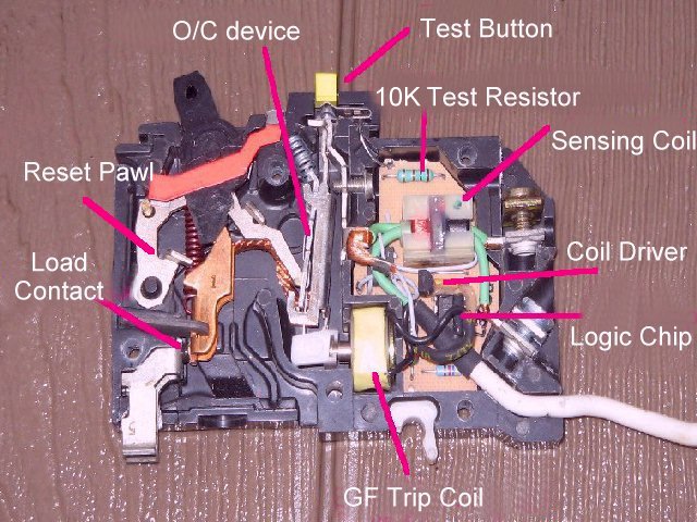
It three light tester will indicate that the circuit is on a GFCI circuit but it does not test the proper level that the test button test at.
The light tester might have a short to ground of far too much amperage than is allowed. It also tests to the equipment grounding conductor not to the source as a true test does.
The test button on the device test for the proper amperage and also does the test to the source for a true imbalance.
David as can be seen by the instructions you posted the government as you referred to states, “Press the “TEST” button on the GFCI outlet.”
This is the only true test that the GFCI device is working at the proper amperage.
I would ask how one is able to get a tester into a two prong receptacle. The original poster stated that the garage had no ground. Was he using three pronged receptacles on circuits without a ground. This is a no-no.
Three prong receptacles should only be used on grounded circuits.
I know here if you have Knob and tube the electric authority recommends you put in a GFCI to protect all receptacles down stream.
I have never seen a two prong GFCI.
I guess the people can seal the Grnd hole with silicone caulk?
The recepticals need to identified as GFCI proteced.
… Cookie
If you have a GFCI, you can use 3 prong receptacles.
This is also one of the rare cases where a ground electrode would be of some value. It would not trip the breaker from an overcurrent but it would trip a GFCI.
The GFCI never trips by use of the grounding electrode or the equipment grounding conductor in normal operation.
What makes it trip is an inblance between the Hot and Neutral conductors. This is why it is not proper to test a GFCI device with one to those plug-in testers.
The garage had 3 prong outlets, clearly labeled that outlets are ungrounded. I did not install the outlets, they were existing at the time of purchase.
It would trip a GFCI if you had a phase or neutral fault to the EGC and that EGC was connected to a ground rod. Normally that would be a fault to the main bonding jumper but on a 2 wire circuit that path is not available. At least, if you had it tied to earth ground you would not have energized equipment waiting for a person to create that imbalance. It would trip the GFCI immediately on the first fault. The case of your equipment would also be at “local ground” potential. That is why we have to drive a rod at a secoind building in the first place.
I agree, the normal fault path is via the EGC to the MBJ but you don’t have that connection here.
As a totally off topic conversation starter, wouldn’t a bootleg ground, connected to a ground electrode be the same as a 250.32(B)(2)???
How about using “wiggys” solenoid type voltage tester? One lead goes to the hot side of the GFCI. The other goes to “Earth” ground (waterpipe, metal faucet, etc.) It had better trip the GFCI
The connection to earth through a grounding electrodes weather a rod, water pipe, concrete encased, ground ring or what ever used to connect to earth plays no role in opening anything be it the fuse, breaker or GFCI device.
The sole purpose of an earth ground is for: 250.4 General Requirements for Grounding and Bonding.
The following general requirements identify what grounding and bonding of electrical systems are required to accomplish. The prescriptive methods contained in Article 250 shall be followed to comply with the performance requirements of this section. (A) Grounded Systems. (1) Electrical System Grounding. Electrical systems that are grounded shall be connected to earth in a manner that will limit the voltage imposed by lightning, line surges, or unintentional contact with higher-voltage lines and that will stabilize the voltage to earth during normal operation.
The purpose of the rod at the second building is the same as it is for the first building and has nothing to do with the operation of any type of safety device be it a fuse, breaker or GFCI.
The overcurrent device opens in a fault condition due to the enormous amount of current being drawn due to the bonding of the equipment grounding conductor back to the neutral at the service.
A GFCI device opens when there is more current on either the hot or the neutral than on the other. The amount of current difference can be no more than .006 amps.
The use of the plug-in tester does not limit the current to .006 amps and sometimes will allow enough current to flow that it will open a 15 amp fuse.
The GFCI device could care less what is causing the imbalance or where the current is going. It only cares that an imbalance of .006 amps or greater exists and if properly installed will open the circuit.
The only true test that the GFCI device is operating at the .006 amps is to use the test button on the device as mentioned in this thread.
For someone to use a plug-in tester and then sign off that the GFCI is working properly is leaving their self open for litigation as these devices are not approved to test GFCI devices.
They are alright to check to see if other receptacles are on a circuit protected by GFCI but it should NEVER be the only test done.
David, why would you think 120v to ground, any ground would not create a 6ma current? Dropping an extension cord in the wet grass seems to defy that notion.
My only point in “grounding” your EGC of a 2 wire connected receptacle if you don’t have a conductor back to the service MBJ is a short to the box WOULD trip the GFCI without having to have a fault through a person.
Lets take the example of the dead kid. If they had that garage door grounded to the earth and a GFCI installed it would have tripped immediately and not waited for a wet kid to complete the circuit.
Might and might not. A rod with more than 2000 ohms would not open the GFCI device.
Is it possible to have an eight foot rod with more than 2000 ohms? Yes especially in my area.
I have driven rods in lab experiments that didn’t open a GFCI breaker
May be true if you are figuring the resistor only but the impedance of the complete circuit will bring it down to the UL requirement of 6 miliamps.
As outlined above it is very possible to have a grounding electrode system with to much resistance to open the GFCI.
An electrode system that has been installed for several years could possibly be deteriorated completely away.
I don’t understand what you are saying here.
If the box is not bonded to the service where will the current go?
This is very iffy. It would depend on the resistance of the soil between the rod and the ground at the transformer.
The bottom line is that a rod DOES NOT operate the GFCI device.