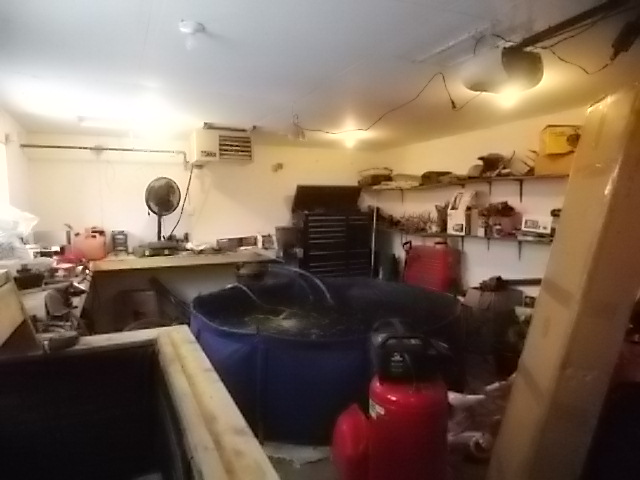
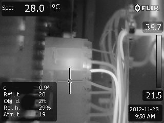
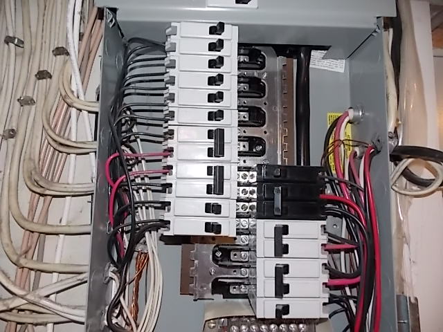
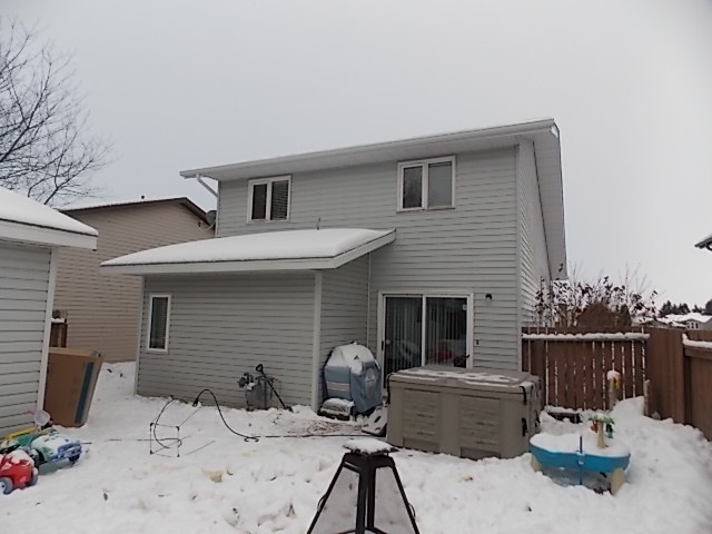
Need a little help on this one. Just came back from an Inspection where I found a 15AMP double poll breaker had the bottom leg 18 degrees celsius hotter then the top leg. The breaker was not marked but I suspect that it is fore the detached garage. The garage was heated, had a 8 foot pool in it for fish. A hottub was outside and also plugged into the garage. Is there a possibility that the garage is drawing enough power on one leg to over heat but not trip the breaker??
There are also double taps in the panel but did not read high.
You can’t really tell if the 18° is significant if you do not know what the load is. Could be a MWBC serving different 120 volt loads. An overload on either leg will trip the CB.
I fully understood you post. At what point do you call it out for further evaluation. I have been told anything more than 20 degrees F is considered high. This one is running at 64.4 degrees F higher than anything else.
With just a visual of what you have I am inclined to beleive that a 15 amp breaker would be overloaded.
Its imparative to know that the amp draw is the same on both legs of a double pole before making a call and no a 20 degrees F rise is not unsual for a unbalanced load. If it was a balanced load then I would call it
By “more than” do you mean on the two legs of the 2 pole CB? In this case your comparison might be the same as comparing the temperature difference between any two randomly selected 1 pole 15 amp CB’s. One of the poles could have a 15 amp load on it and the other a 1 amp load. That would give you quite a difference in temperature between the two conductors. The question should be if one pole has a significant load on it what should the normal conductor temperature be.
Correct sir. But what should that temperature be? Guess I am trying to figure out if I should be calling it up. My gut says I should but it’s been wrong before.
I don’t do thermal imaging so I will defer to someone who does.
You need to know what a normal operating temperature is for the load on the conductor. Comparing the two conductors attached to the 2 pole CB in this case tells you nothing.
The furnace was running, The stove was on and every light it in the home. When I do my inspections I try to load the panel as much as possible. I have never seen this so that why I come to the guru’s.:)
I have had transformer windings @ 250 degrees F perferctly normal Robert is correct you must know the load on each leg before making a call. its easy on a cookstove because the amps are the same on both sides. Take a main breaker Rated at 100 amps and the panel is loaded one side with 25 amps and the other side at 50 amps your going to see a significant difference but it is normal. Your 65 F can be perfectly normal for the load but without the amp draw you have know way of compaging.
Thermal imaging in electrical is all about comparsion
Are you say you don’t know what the breaker serves turn the dang thing off and find out Where is your amp meter its just as important as the IR camera without it the IR camera and electricalis useless
Without taking load readings, your options are pretty limited. Since we cannot compare to a similar component under similar load or apply an absolute temperature criteria, we’re relegated to comparing our suspect exception to apparent ambient temperature.
Using the NETA Maintenance Testing Criteria, we get a Priority 3 “Probable deficiency; repair as time permits” for our possible exception.
So, what does the thermal pattern you observed tell you about the likely cause of the temperature rise (loose or high resistance connection; failing component; load; other)? Why?
BTW: I would not use the term “over heat”. The apparent temperatures that you observed are a long way from overheating anything. Better to refer to it as a “thermal exception”.
Unfortunately an 18° C temperature differential does not equate to a 64° F temperature differential.
64° F is simply the direct conversion of a sole/lone temperature measurement of 18° C
This is a common mistake in converting temperatures and temperature differentials. An 18° C delta is actually equivalent to 32.4° F delta.
The true difference in temperatures should be comparison between similar components or true ambient conditions and not simply the “coolest” exception in the image or area box.
The difference calculated from the image (whether correctly or incorrectly) appears relatively minor, but as others have stated… crucial information is missing namely the actual load and rated load of the component(s) showing the thermal exception(s). Without the crucial information, it’s really anyone’s guess if this is a problem or not and what the potential severity may be.