I am in search of a good diagram to use in reports for a multi-wire branch circuit. To convey to the client what this is in a simple, intuitive, user-friendly diagram. A good diagram would also show the need for a handle tie on these circuits. I have scoured to the deepest depths of the internet (scary places!) and have not been able to find one that would be suitable for a client that might not know much about electricity.
Anyone have a good one? @rmayo do you have any interest in taking this on?
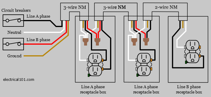
The image below is fairly close to what I think would be useful. I think starting from this, it would be great to show that the red, black, and white conductors are all in one sheathing (a cable assembly). And make it more clear that the red and black conductors land on different breakers. Then labeling to say that the circuits share a grounded conductor. Could also add an EGC to the diagram but that probably isn’t a must have and may just add confusion. Then of course labeling showing that the two separate breakers need handle ties.
I think that you’re on the right track with Mike’s graphic. Given that your target audience is homeowners I would use the term neutral instead of grounded conductor.
A good graphic of this would be great! It’s so hard to describe how these circuits work.
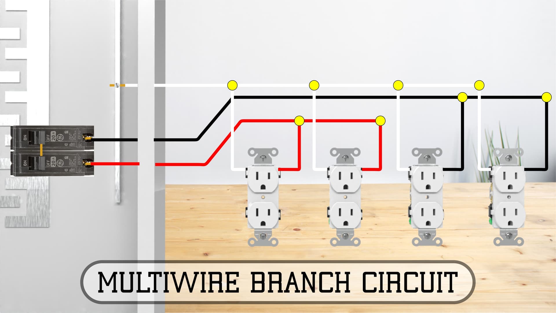
A couple thoughts to simplify it further:
Just one outlet on each circuit.
Showing them on opposite sides of the neutral conductor so there are fewer points with wires crossing each other. Plus I think it would be easier to visualize the idea of the idea of the loads balancing each other.
First image I came to on google. What eactly is the idea you are trying to convey through this image? We have Inspectors who don’t understand the significance of multi-wire circuits.
I think you may be overlooking the fact that the average homeowner doesn’t understand basic electricity. Without a little background they’re not going to grasp a shared neutral; graphic or no graphic. “When someone asks you for the time, they don’t want to know how to build a watch.”
The question I get most often is simply, “Is it safe?” That’s all they want to know.
I don’t really need them to fully understand the concept. I just need them to be able to visualize what my narrative is telling them. And in the rare case a client or their agent calls because they want to understand the issue better, I can have them pull up the report and view the image as I go over it in more detail. Just a nice-to-have thing.
I overlooked the ISO in your title. I now know wat you meant, but ISO is the Abbreviation of the International Organization of Standards. You might need a graphic to explain you meant IN Search OF.
Good discussion. For the illustration, terms like “Hot” or “Black”, “Return wire or path” or “White”, and “Ground” or “Bare” are the way most clients understand it. But it is pretty hard to have an illustration that adequately explains wiring and is still simple.
I was just pointing out an error in the graphic but you’re correct that the circuits to the receptacle on the right of your graphic aren’t germane to a MWBC. Handle ties are germane to what Ryan is trying to accomplish with this new graphic.