Learn what to look for when checking water pressure and flow during a home inspection. Understand what code requires and how to determine if the home you’re inspecting meets minimum standards. Gain practical, field-tested tips every inspector should know.
Want more videos like this one? Check out our YouTube Channel for more!
It’s not quite that simple the Code indicates the plumbing shall be designed to perform under peak demand. Unless all the other fixtures in the structure were running when that video was recorded, that measurement technique would not be accurate.
P2903.1 Water supply system design criteria.
The water service and water distribution systems shall be designed and pipe sizes shall be selected such that under conditions of peak demand, the capacities at the point of outlet discharge shall not be less than shown in Table P2903.1.
An issue we have in GA. Notably older homes, the front hose bib is connected to the supply pipe before the pressure regulator. Therefore, any measurement there is municipal supply pressure/flow and not representative of the remainder of the home.
There are calculations in the Code for pipe sizing to meet required flow in Chapter 29 and Appendix P. Here is a small sample from Appendix P…
Easy peasy
AP103.2 Pipe sizing.
AP103.2.1
Pipe sizes can be selected using the following procedure or by use of other design methods conforming to acceptable engineering practice that are approved by the building official. The sizes selected must not be less than the minimum required by this code.
AP103.2.2
Water pipe sizing procedures are based on a system of pressure requirements and losses, the sum of which must not exceed the minimum pressure available at the supply source. These pressures are as follows:
1.Pressure required at fixture to produce required flow. See Sections P2903.1 of this code and Section 604.3 of the Florida Building Code, Plumbing.
2.Static pressure loss or gain (due to head) is computed at 0.433 psi per foot (9.8 kPa/m) of elevation change.Example: Assume that the highest fixture supply outlet is 20 feet (6096 mm) above or below the supply source. This produces a static pressure differential of 8.66 psi (59.8 kPa) loss [20 feet by 0.433 psi per foot (2096 mm by 9.8 kPa/m)].
3.Loss through water meter. The friction or pressure loss can be obtained from meter manufacturers.
4.Loss through taps in water main.
5.Loss through special devices, such as filters, softeners, backflow prevention devices and pressure regulators. These values must be obtained from the manufacturer.
6.Loss through valves and fittings. Losses for these items are calculated by converting to the equivalent length of piping and adding to the total pipe length.
7.Loss caused by pipe friction can be calculated where the pipe size, pipe length and flow through the pipe are known. With these three items, the friction loss can be determined. For piping flow charts not included, use manufacturers’ tables and velocity recommendations.
Note: For all examples, the following metric conversions are applicable.
1 cubic foot per minute = 0.4719 L/s.
1 square foot = 0.0929 m2.
1 degree = 0.0175 rad.
1 pound per square inch = 6.895 kPa.
1 inch = 25.4 mm.
1 foot = 304.8 mm.
1 gallon per minute = 3.785 L/m.
AP103.3 Segmented loss method.
The size of water service mains, branch mains and risers by the segmented loss method, must be determined by knowing the water supply demand [gpm (L/m)], available water pressure [psi (kPa)] and friction loss caused by the water meter and developed length of pipe [feet (m)], including the equivalent length of fittings. This design procedure is based on the following parameters:
1.The calculated friction loss through each length of pipe.
2.A system of pressure losses, the sum of which must not exceed the minimum pressure available at the street main or other source of supply.
3.Pipe sizing based on estimated peak demand, total pressure losses caused by difference in elevation, equipment, developed length and pressure required at the most remote fixture; loss through taps in water main; losses through fittings, filters, backflow prevention devices, valves and pipe friction.
Because of the variable conditions encountered in hydraulic design, it is impractical to specify definite and detailed rules for the sizing of the water piping system. Current sizing methods do not address the differences in the probability of use and flow characteristics of fixtures between types of occupancies. Creating an exact model of predicting the demand for a building is impossible and final studies assessing the impact of water conservation on demand are not yet complete. The following steps are necessary for the segmented loss method.
1.Preliminary. Obtain the necessary information regarding the minimum daily static service pressure in the area where the building is to be located. If the building supply is to be metered, obtain information regarding friction loss relative to the rate of flow for meters in the range of sizes to be used. Friction loss data can be obtained from manufacturers of water meters. Enough pressure must be available to overcome all system losses caused by friction and elevation so that plumbing fixtures operate properly. Section 604.6 of the Florida Building Code, Plumbing requires that the water distribution system be designed for the minimum pressure available taking into consideration pressure fluctuations. The lowest pressure must be selected to guarantee a continuous, adequate supply of water. The lowest pressure in the public main usually occurs in the summer because of lawn sprinkling and supplying water for air-conditioning cooling towers. Future demands placed on the public main as a result of large growth or expansion should be considered. The available pressure will decrease as additional loads are placed on the public system.
2.Demand load. Estimate the supply demand of the building main and the principal branches and risers of the system by totaling the corresponding demand from the applicable part of Table AP103.3(3). When estimating peak demand, sizing methods typically use water supply fixture units (w.s.f.u.) [see Table AP103.3(2)]. This numerical factor measures the load-producing effect of a single plumbing fixture of a given kind. The use of fixture units can be applied to a single basic probability curve (or table), found in the various sizing methods [see Table AP103.3(3)]. The fixture units are then converted into a gpm (L/m) flow rate for estimating demand.
2.1.Estimate continuous supply demand in gpm (L/m) for lawn sprinklers, air conditioners, etc., and add the sum to the total demand for fixtures. The result is the estimated supply demand for the building supply. Fixture units cannot be applied to constant-use fixtures, such as hose bibbs, lawn sprinklers and air conditioners. These types of fixtures must be assigned the gpm (L/m) value.
3.Selection of pipe size. This water pipe sizing procedure is based on a system of pressure requirements and losses, the sum of which must not exceed the minimum pressure available at the supply source. These pressures are as follows:
3.1.Pressure required at the fixture to produce required flow. See Section P2903.1 of this code and Section 604.3 of the Florida Building Code, Plumbing.
3.2.Static pressure loss or gain (because of head) is computed at 0.433 psi per foot (9.8 kPa/m) of elevation change.
3.3.Loss through a water meter. The friction or pressure loss can be obtained from the manufacturer.
3.4.Loss through taps in water main [see Table AP103.3(4)].
3.5.Loss through special devices, such as filters, softeners, backflow prevention devices and pressure regulators. These values must be obtained from the manufacturers.
3.6.Loss through valves and fittings [see Tables AP103.3(5) and AP103.3(6)]. Losses for these items are calculated by converting to the equivalent length of piping and adding to the total pipe length.
3.7.Loss caused by pipe friction can be calculated where the pipe size, pipe length and flow through the pipe are known. With these three items, the friction loss can be determined using Figures AP103.3(2) through AP103.3(7). Where using charts, use pipe inside diameters. For piping flow charts not included, use manufacturers’ tables and velocity recommendations. Before attempting to size any water supply system, it is necessary to gather preliminary information including available pressure, piping material, select design velocity, elevation differences and developed length to the most remote fixture. The water supply system is divided into sections at major changes in elevation or where branches lead to fixture groups. The peak demand must be determined in each part of the hot and cold water supply system. The expected flow through each section is determined in w.s.f.u. and converted to gpm (L/m) flow rate. Sizing methods require determination of the “most hydraulically remote” fixture to compute the pressure loss caused by pipe and fittings. The hydraulically remote fixture represents the most downstream fixture along the circuit of piping requiring the most available pressure to operate properly. Consideration must be given to all pressure demands and losses, such as friction caused by pipe, fittings and equipment; elevation; and the residual pressure required by Table P2903.1. The two most common and frequent complaints about water supply system operation are lack of adequate pressure and noise.
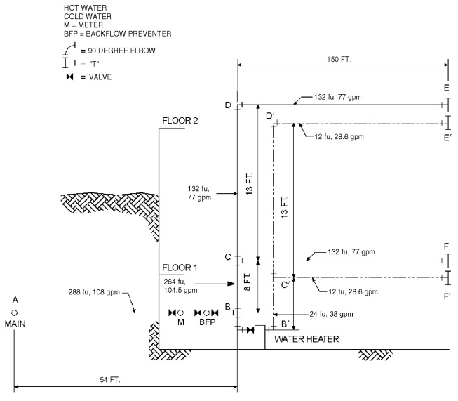
Problem: What size Type L copper water pipe, service and distribution will be required to serve a two-story factory building having on each floor, back-to-back, two toilet rooms each equipped with hot and cold water? The highest fixture is 21 feet above the street main, which is tapped with a 2-inch corporation cock at which point the minimum pressure is 55 psi. In the building basement, a 2-inch meter with a maximum pressure drop of 11 psi and 3-inch reduced pressure principle backflow preventer with a maximum pressure drop of 9 psi are to be installed. The system is shown in Figure AP103.3(1). To be determined are the pipe sizes for the service main, and the cold and hot water distribution pipes.
Solution: A tabular arrangement such as shown in Table AP103.3(1) should first be constructed. The steps to be followed are indicated by the tabular arrangement itself as they are in sequence, Columns 1 through 10 and Lines A through L.
Step 1
Columns 1 and 2: Divide the system into sections breaking at major changes in elevation or where branches lead to fixture groups. After Point B [see Figure AP103.3(1)], separate consideration will be given to the hot and cold water piping. Enter the sections to be considered in the service and cold water piping in Column 1 of the tabular arrangement. Column 1 of Table AP103.3(1) provides a line-by-line, recommended tabular arrangement for use in solving pipe sizing.
The objective in designing the water supply system is to ensure an adequate water supply and pressure to all fixtures and equipment. Column 2 provides the psi (kPa) to be considered separately from the minimum pressure available at the main. Losses to take into consideration are the following: the differences in elevations between the water supply source and the highest water supply outlet; meter pressure losses; the tap in main loss; special fixture devices, such as water softeners and backflow prevention devices; and the pressure required at the most remote fixture outlet.
The difference in elevation can result in an increase or decrease in available pressure at the main. Where the water supply outlet is located above the source, this results in a loss in the available pressure and is subtracted from the pressure at the water source. Where the highest water supply outlet is located below the water supply source, there will be an increase in pressure that is added to the available pressure of the water source.
Column 3: Using Table AP103.3(3), determine the gpm (L/m) of flow to be expected in each section of the system. These flows range from 28.6 to 108 gpm. Load values for fixtures must be determined as w.s.f.u. and then converted to a gpm rating to determine peak demand. Where calculating peak demands, the w.s.f.u. are added and then converted to the gpm rating. For continuous flow fixtures, such as hose bibbs and lawn sprinkler systems, add the gpm demand to the intermittent demand of fixtures. For example, a total of 120 w.s.f.u. is converted to a demand of 48 gpm. Two hose bibbs × 5 gpm demand = 10 gpm. Total gpm rating = 48.0 gpm + 10 gpm = 58.0 gpm demand.
Step 2
Line A: Enter the minimum pressure available at the main source of supply in Column 2. This is 55 psi (379.2 kPa). The local water authorities generally keep records of pressures at different times of the day and year. The available pressure can also be checked from nearby buildings or from fire department hydrant checks.
Line B: Determine from Table P2903.1 the highest pressure required for the fixtures on the system, which is 15 psi (103.4 kPa), to operate a flushometer valve. The most remote fixture outlet is necessary to compute the pressure loss caused by pipe and fittings, and represents the most downstream fixture along the circuit of piping requiring the available pressure to operate properly as indicated by Table P2903.1.
Line C: Determine the pressure loss for the meter size given or assumed. The total water flow from the main through the service as determined in Step 1 will serve to aid in the meter selected. There are three common types of water meters; the pressure losses are determined by the American Water Works Association Standards for displacement type, compound type and turbine type. The maximum pressure loss of such devices takes into consideration the meter size, safe operating capacity [gpm (L/m)] and maximum rates for continuous operations [gpm (L/m)]. Typically, equipment imparts greater pressure losses than piping.
Line D: Select from Table AP103.3(4) and enter the pressure loss for the tap size given or assumed. The loss of pressure through taps and tees in psi (kPa) is based on the total gpm (L/m) flow rate and size of the tap.
Line E: Determine the difference in elevation between the main and source of supply and the highest fixture on the system. Multiply this figure, expressed in feet (mm), by 0.43 psi. Enter the resulting psi (kPa) loss on Line E. The difference in elevation between the water supply source and the highest water supply outlet has a significant impact on the sizing of the water supply system. The difference in elevation usually results in a loss in the available pressure because the water supply outlet is generally located above the water supply source. The loss is caused by the pressure required to lift the water to the outlet. The pressure loss is subtracted from the pressure at the water source. Where the highest water supply outlet is located below the water source, there will be an increase in pressure that is added to the available pressure of the water source.
Lines F, G and H: The pressure losses through filters, backflow prevention devices or other special fixtures must be obtained from the manufacturer or estimated and entered on these lines. Equipment, such as backflow prevention devices, check valves, water softeners, instantaneous, or tankless water heaters, filters and strainers, can impart a much greater pressure loss than the piping. The pressure losses can range from 8 to 30 psi.
Step 3
Line I: The sum of the pressure requirements and losses that affect the overall system (Lines B through H) is entered on this line. Summarizing the steps, all of the system losses are subtracted from the minimum water pressure. The remainder is the pressure available for friction, defined as the energy available to push the water through the pipes to each fixture. This force can be used as an average pressure loss, as long as the pressure available for friction is not exceeded. Saving a certain amount for available water supply pressures as an area incurs growth, or because of the aging of the pipe or equipment added to the system is recommended.
Step 4
Line J: Subtract Line I from Line A. This gives the pressure that remains available from overcoming friction losses in the system. This figure is a guide to the pipe size that is chosen for each section, incorporating the total friction losses to the most remote outlet (measured length is called developed length).
Exception: Where the main is above the highest fixture, the resulting psi (kPa) must be considered a pressure gain (static head gain) and omitted from the sums of Lines B through H and added to Line J.
The maximum friction head loss that can be tolerated in the system during peak demand is the difference between the static pressure at the highest and most remote outlet at no-flow conditions and the minimum flow pressure required at that outlet. If the losses are within the required limits, every run of pipe will be within the required friction head loss. Static pressure loss is at the most remote outlet in feet × 0.433 = loss in psi caused by elevation differences.
Step 5
Column 4: Enter the length of each section from the main to the most remote outlet (at Point E). Divide the water supply system into sections breaking at major changes in elevation or where branches lead to fixture groups.
Step 6
Column 5: Where selecting a trial pipe size, the length from the water service or meter to the most remote fixture outlet must be measured to determine the developed length. However, in systems having a flushometer valve or temperature-controlled shower at the topmost floors, the developed length would be from the water meter to the most remote flushometer valve on the system. A rule of thumb is that size will become progressively smaller as the system extends farther from the main source of supply. A trial pipe size can be arrived at by the following formula:
Line J: (Pressure available to overcome pipe friction) × 100/equivalent length of run total developed length to most remote fixture × percentage factor of 1.5 (Note: a percentage factor is used only as an estimate for friction losses imposed for fittings for initial trial pipe size) = psi (average pressure drop per 100 feet of pipe).
For trial pipe size, see Figure AP103.3(3) (Type L copper) based on 2.77 psi and 108 gpm = 21/2 inches. To determine the equivalent length of run to the most remote outlet, the developed length is determined and added to the friction losses for fittings and valves. The developed lengths of the designated pipe sections are as follows:
A-B
54 feet
B-C
8 feet
C-D
13 feet
D-E
150 feet
Total developed length = 225 feet
The equivalent length of the friction loss in fittings and valves must be added to the developed length (most remote outlet). Where the size of fittings and valves is not known, the added friction loss should be approximated. A general rule that has been used is to add 50 percent of the developed length to allow for fittings and valves. For example, the equivalent length of run equals the developed length of run (225 feet × 1.5 = 338 feet). The total equivalent length of run for determining a trial pipe size is 338 feet.
Example: 9.36 (pressure available to overcome pipe friction) × 100/338 (equivalent length of run = 225 × 1.5) = 2.77 psi (average pressure drop per 100 feet of pipe).
Step 7
Column 6: Select from Table AP103.3(6) the equivalent lengths for the trial pipe size of fittings and valves on each pipe section. Enter the sum for each section in Column 6. (The number of fittings to be used in this example must be an estimate). The equivalent length of piping is the developed length plus the equivalent lengths of pipe corresponding to the friction head losses for fittings and valves. Where the size of fittings and valves is not known, the added friction head losses must be approximated. An estimate for this example is found in Table AP.1.
Step 8
Column 7: Add the figures from Columns 4 and 6, and enter in Column 7. Express the sum in hundreds of feet.
Step 9
Column 8: Select from Figure AP103.3(3) the friction loss per 100 feet of pipe for the gpm flow in a section (Column 3) and trial pipe size (Column 5). Maximum friction head loss per 100 feet is determined on the basis of the total pressure available for friction head loss and the longest equivalent length of run. The selection is based on the gpm demand, uniform friction head loss and maximum design velocity. Where the size indicated by the hydraulic table indicates a velocity in excess of the selected velocity, a size must be selected that produces the required velocity.
Step 10
Column 9: Multiply the figures in Columns 7 and 8 for each section and enter in Column 9.
Total friction loss is determined by multiplying the friction loss per 100 feet for each pipe section in the total developed length by the pressure loss in fittings expressed as equivalent length in feet (mm). Note: Section C-F should be considered in the total pipe friction losses only if greater loss occurs in Section C-F than in pipe Section D-E. Section C-F is not considered in the total developed length. Total friction loss in equivalent length is determined in Table AP.2.
Step 11
Line K: Enter the sum of the values in Column 9. The value is the total friction loss in equivalent length for each designated pipe section.
Step 12
Line L: Subtract Line J from Line K and enter in Column 10.
The result should always be a positive or plus figure. If it is not, repeat the operation using Columns 5, 6, 8 and 9 until a balance or near balance is obtained. If the difference between Lines J and K is a high positive number, it is an indication that the pipe sizes are too large and should be reduced, thus saving materials. In such a case, the operations using Columns 5, 6, 8 and 9 should be repeated.
The total friction losses are determined and subtracted from the pressure available to overcome pipe friction for the trial pipe size. This number is critical because it provides a guide to whether the pipe size selected is too large and the process should be repeated to obtain an economically designed system.
Answer: The final figures entered in Column 5 become the design pipe size for the respective sections. Repeating this operation a second time using the same sketch but considering the demand for hot water, it is possible to size the hot water distribution piping. This has been worked up as a part of the overall problem in the tabular arrangement used for sizing the service and water distribution piping. Note that consideration must be given to the pressure losses from the street main to the water heater (Section A-B) in determining the hot water pipe sizes.