Hot outlet - Vacant House

Been awhile since I’ve posted any pics…Vacant house… HVAC running, but not on this branch.

Plugged in tester, noticed it was a bit hot. Took thermal pic of outlet… noted outlet on opposite side of wall and a few feet away was warm, and cable unhappy

Would have noted the hot outlet, but IR gave a bit more info.

Hot outlet.jpg

Hot outlet.jpg

Opposite of hot outlet.jpg

Was it visible:smiley:

IR_0863_panorama.jpg

I’ll take a stab at it Tim.

First off I’m untrained in IR so this is a WAG.

My guess is missing insulation. and being you’re in the high desert it was one of those day’s where the wind was blowing like a blow dryer on high, which blew the hot air into the cavities and leak paths in the wall. :slight_smile:

so…

What was on that circuit?

Well, at times that can be the case (blow dryer effect) :smiley:

In first example… outlets and connected branch wiring HOT, vacant home/no load beyond some lights, unless the FAU is wired into the branch for bedrooms/living… new enough home and FAU labeled as having own circuit. Seemed to involve 2 receptacles and associated wiring.

Second picture, moisture was found at time of wall during cursory scan… been very dry here, and a light rain had occurred 4 days or so prior to inspection… 40-50+% RH measured.

No known load, vacant home, built in the 90’s

Conv circuit for living and sleeping areas. Hardly a light on

Fau had own circuit and was running along with condenser

Is this hot enough?

Good deal Peter… Visual of that one?

Tim, you do realize that your post #1 has nothing to do with electrical overheating, right?!

It did… turned out FAU was on said circuit (builder had option of 3rd car/bonus), and I was told failing motor for air handler… circuit was serving living areas, and shouldn’t. I would assume weak connection(s) at outlets pictured as well, but apparently were checked out. <– We’re lucky to get any feedback.

I’m curious though, this was an interior wall, on the first floor of a 2 story. What other causes come to mind when looking at something like this? No plumbing in this wall.

I would recommend in the future that when you are talking about thermal anomalies using thermal imaging that you continue your investigation (to industry standard) and determine the amperage draw on the circuits that are hot.

You can go back to the service panel and find the same hot wire that you found in the wall.

Take an amperage reading. If you don’t have an amperage meter, get one because you own a thermal camera and you need one.

Can’t do thermal imaging without one. Otherwise you are guessing and assuming.

Here is that damn word again!

You could have solved everybody’s problem without deferral, without guessing, without assuming and without depending on some other idiot that caused the problem to start with, to try to fix it.

Good points David, and yes I have an amp meter. Through TI, the buyer was made aware of concerns that would likely have gone unnoticed. FWIW, I wasn’t asking a question just sharing and opening a discussion.

Still wondering, you indicated that you thought it obvious this may have been another problem altogether based on the image, I am curious what you had in mind. I’m always happy to learn more and from a different point of view. Thanks!

Based on your “weather zone”, outdoor ambient temperatures and indoor attic temperatures can be significant.

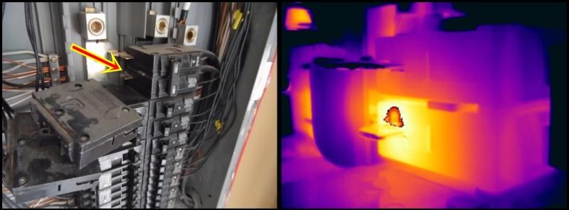
The coldest color in your scan (blue) is 83°. So it had to have been a hot day.

Attic temperatures can easily exceed 150° as it did in my inspection yesterday.

Wiring displaces insulation and causes convective pathways through the wall.

Building depressurization such as with air duct leakage will significantly draw air from the attic spaces through the plug outlets and give you the same pattern that you have here.

You stated the HVAC was in fact running. 95% of all HVAC systems have 20 to 30 % air leakage.

You indicated that nothing was turned on except the HVAC. Based upon this information I would lean more towards convective heat transfer.

I’m still not actually convinced that your load was creating this much heat. The pattern is just too wide. Overheated electrical conductors are generally much smaller than this.

You have a meter. Did you take the amperage draw on the circuit? We can calculate a temperature rise based upon this you realize.

My point was, if you took the required amperage reading to determine the load on the overheated circuit under thermal imaging standards you would have determined the amperage draw on the circuit and could find the source with the same amp draw.

I also question “follow-up information” from the contractors (that are ones that created the situation in the first place). Did they really trace out the circuit or did they just find another problem and assume that they were connected?

I’m assuming a lot of information, but it is information you stated.

As for assuming, I would not assume a loose connection either.

I know this will scare the crap out of some of you…

But in my opinion when you pull out a thermal imaging camera on a home inspection you need to disregard your home inspection nonsense standard and start pulling things apart because I will assure you that no electrician is going to do it for you.

Yes, I do practice what I preach:

http://i572.photobucket.com/albums/ss162/dandersen_02/7b4.jpg

http://i572.photobucket.com/albums/ss162/dandersen_02/7b5.jpg

This was 156F on a 100 Amp Breaker at this load in a 90F panel.

Can someone tell me what the apparent temperature rise will be at 80% capacity?

Also, can we justify this temperature rise between L1 and L2 at this unbalanced load?

http://i572.photobucket.com/albums/ss162/dandersen_02/ScreenHunter_08Jul061634.jpg