Hi. Frank;
I understand where you are coming from, but there is a possibility that the bearing wall was installed as designed and would be no different than a beam underneath the floor system.
Here is an interesting article that I found, a little lengthy, but interesting.
by J.D. Grewell
Having performed framing (pre-drywall or close-in) inspections for 30 years, I recently became aware of confusion regarding the newer floor framing systems. It appears some of it can be traced to foremen and site superintendents who are tasked to the maximum, have limited authority on the job site, and often have only minimal understanding of architectural plans, especially related to the floor framing systems.
Another factor may be a practice that is commonplace in my area. Often builders have one approved master plan for each floor plan they sell, and do not change the plan or correct it to as built after rooms are added or made larger to please the client. This practice creates a problem for those who are trying to build the structure, as well for those hired to evaluate it.
THE BASICS OF FRAMING
As a youngster, my grandfather taught me what I needed to know about framing. I learned a point load is the concentration of the weight of the structure above an area. For instance, consider the framing above a wide doorway. Generally there will be two 2" x 10" headers. The ends of the headers must be supported. In most cases there will be a minimum of two 2" x 4" studs. What lies below these stress points?
To understand the load in relation to roofs and walls, step back and ask; “What holds this up and where does all the weight (load) end up?” Sometimes it takes several trips from floor to floor to determine the answer, and in recent years I have discovered far too often necessary supports have been forgotten or omitted.
My grandfather also taught me a simple span table that I still use sometimes as a starting point for a framing inspection. But with the advent of open web truss and wood I-joist construction, a different set of rules became necessary for these designs. Anyone who is not familiar with building codes and span tables ought to study them and understand the minimums for dimensional lumber before doing framing inspections. The Western Wood Products Association (www.wwapa.org) offers seminars covering the rating of lumber and its proper use concerning span tables for the various species. Information is also available from The American Wood Council (www.awc.org), and the American Forest and Paper Association (www.afandpa.org).
Almost all wood I-joist manufacturers have their own Web sites, and all have technical catalogues tradesmen are supposed to comprehend and follow.
THE MORE COMPLEX THE CONSTRUCTION THE GREATER THE RISK OF ERROR
Many newer homes have elaborate rooflines and steep pitches that lead to framing errors, and great rooms with soaring cathedral ceilings only complicate things further. Thankfully, houses rarely collapse, but over time they will and do move. Sometimes the faults become apparent through sagging ceilings and drywall fractures. Repairs often require destructive analysis procedures followed by engineered design repairs, which are costly corrective measures.
Most homes with steep pitches use 2" x 4" and 2" x 6" manufactured trusses, which end up having to be stacked atop each other, sometimes three high (called piggyback trusses in the trades). Stacked trusses must be properly aligned and braced. The Truss Plate Institute (www.tpinst.org) provides superior information about truss roof design and installation requirements.
Frequently truss girders are used to create the elaborate rooflines. These are ganged sets of trusses. Proper nailing must be performed because the base chord often is used to carry a vast roof load from an adjoining roofing section. This is usually where a large expansive gable ties into the primary roof. The front-to-rear trusses intersect the gable trusses. Here is where the front-to-rear bonding occurs through the use of joist hanger-like connections (www.stongtie.com). The hangers must also be properly nailed with approved nails.
http://www.inspectorsjournal.com/forum/uploads/hausdok/2006613123559_IjoistsFigure1small.JPGGirder truss members often terminate atop a framed bearing wall with a double top plate, sometimes at intersecting corners. Girder trusses are laminations of three or more members having a combined thickness of 6"-8". There should be at least as many studs forming a post below these load transfer points, hence the term point load. (See Figure 1) The loads must then be picked up below the bottom plate and subfloor, all the way down to the foundation. These point load construction details show up as darkened blocked areas on most plans, usually with a detail somewhere specifying the needed supports. I’ve pointed this out to foremen only to have them reply, “So that’s what this means.” In my experience code inspectors miss these details as well.
LOOK FOR LOAD TRANSFER POINTS
So, when you’re out on the job at a framing inspection, start with the roof and look for load transfer points. http://www.inspectorsjournal.com/forum/uploads/hausdok/20066131309_IjoistsFigure2small.JPGSometimes you will find loads transferred from one point to another through beams. (See Figure 2) This practice only concentrates loads. On occasion I have found loads transferred to a central point only to find no supporting structure at the floor level below. Point loads should never terminate on a subfloor unless there is direct contact to bearing points below and never simply mid-bay of the joists. Occasionally this occurs and the subfloor or joist obviously bows downward. When this happens it requires a review of the design by a qualified licensed structural engineer to design a repair method.
With conventional floor framing, placing joists side-by-side (sistering, doubling, forming trimmers and headers) or within 6 inches of each other forms a beam. Early framers used single trimmers and headers at staircases, leading to sagging, sometimes quite significantly. In older homes this becomes part of their charm and character of the home. The carpentry profession learned from experience to double these members to limit the sagging potentials by creating trimmer joists and headers for staircases.
The same learning was applied to placing doubles below partition walls. This is exceedingly rare to find in my area of the country anymore. Thankfully at least walls usually align with joists. If not, it’s usually because of a convoluted or complex room layout. Even a non-load bearing wall resting between joist bays on the subfloor can cause the floor to bend and drywall to crack. Often new homes are covered by a one-year warranty, and the homeowner discovers this error within the first year, but not always.
ENGINEERED JOISTS PLUS OTHER PRODUCTS FORM A SYSTEM
With the advent of engineered floor framing systems, prior rules generally do not apply. The two predominant types of engineered joists are wood I-joists and open-web truss joists consisting of 2" x 4" lumber usually with steel gussets where the chords intersect, similar to truss roof members. I strongly encourage inspectors to visit the Web sites of the Engineered Wood Association (www.apawood.com) and of TrusJoist McMillan (www.tjm.com) who did the majority of the engineering of the first wood I-joists by developing the Silent Floor System. Other national and local fabricators quickly copied these types of joists. Most provide design capabilities, and for a fee will review the plans and specify the centers, placement, spans, and the types of hangers (www.strongtie.com) to be used.
Most of these same firms also manufacture band boards, microlams, paralams, and other engineered beams. All of these products are used in concert to form a system. Mixing manufacturers’ products is an extremely poor practice that can compromise the structural integrity of the building and can void the manufacturers’ warranties.
All manufacturers of these flooring systems publish specification booklets showing how these systems are to be used. They employ the international road sign symbols to mark detailed drawings of prohibited practices. These prohibitions are sometimes ignored, misunderstood, or violated by the installing contractors. All too often the other trades damage or compromise the structure while performing their task or installing their system.
These wood I-joists are superior to framing lumber in many regards; however, they allow more bending or flex than the old 2" x 10" type rules. Most often, the contractors, even though they are allowed to put them at 12-inch, 16-inch, 19.2-inch and 24-inch centers, place them on the maximum span. This allows and fosters, in some cases, excessive flex. A simple way to test this is to jump on the floor. If it feels like a trampoline, something is wrong. These joists are lighter in weight, and they allow greater span potentials, but only when installed as specified by the designers. The Engineered Wood Association’s Web site (apawood.org) is often more helpful than the manufacturer’s booklets at this point. It offers large drawings accompanied by excellent descriptions explaining why specific materials are needed to form the flooring system.
SPECIFIC MATERIALS ARE REQUIRED FOR A FUNCTIONING SYSTEM
Some of the materials required for a functioning system have odd sounding names, such as web stiffener, squash block, blocking panel, and fillers. All are highly critical in making the system interlock and function as a web, or box construction. To perform framing inspections it is equally as critical to understand the why and where of these components as it is to understand point loads. Doubled wood I-joists that act as trimmers, beams and girders or as headers need these fillers. Without the fillers the parallel joists are simply parallel, not joined to make a beam. A filler is conventional framing lumber placed between the webs of the I-joists to fill the cavity. When the wood I-joists are then properly nailed together, through the web from both faces, proper bonding renders them as a structural member.
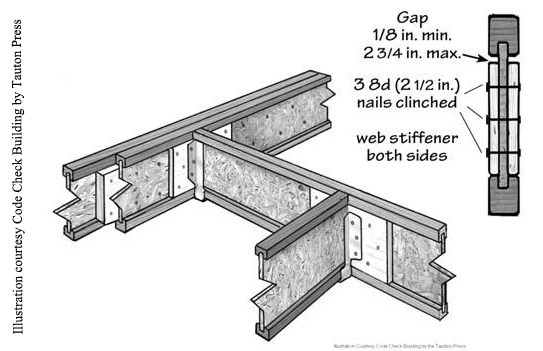
http://www.inspectorsjournal.com/forum/uploads/hausdok/2006613132939_IjoistsIllustration1small.jpg Where these joists intersect perpendicular to each other, as in a header See Illustration 1), web stiffeners are also needed to keep the hangers from bending and to assist in keeping the wood flush. Web stiffeners are rectangular pieces of plywood, or oriented strand board (OSB) that are placed between the I-joist’s flanges and the butted webs as a filler material.
Where wood I-joists lap or cross over a girder, beam or framed bearing wall, (depending on loads from above), the flanges must be protected from being crushed. Squash blocks and blocking panels serve this purpose (See Illustration 2). Squash blocks are pieces of 2" x 4" placed vertically on each side of the joist. These must be 1/16 inch taller than the top (compression) flange of the wood I-joist. Blocking panels are the same material as the wood I-joist but are set in place between the joists parallel with the beam. This spreads the floor loads fully onto the beam.
http://www.inspectorsjournal.com/forum/uploads/hausdok/2006613135341_IjoistsIllustration2small.JPGBlocking panels and squash blocks are sometimes removed by plumbing and heating contractors to facilitate the placement of their equipment and materials. When these are removed, the framing carpenters are supposed to be informed the structure has been altered so the framers can make the necessary corrections. In my experience, this communication rarely occurs. If code officials conduct the framing inspection before the mechanical inspection, they can’t catch it. Also some code inspectors lack a full understanding of the newer flooring systems, and do not notice that squash blocks are missing or that blocking panels were removed or altered. Not only will problems develop because of these errors, but the manufacturer’s lifetime warranty will not cover a flooring system that is missing required materials or is otherwise not installed as designed.
MORE DO’S AND DON’TS
The top and bottom flanges of these joists (compression and tension respectively)should never be notched (See Illustration 3), cut (See Illustration 4), drilled (See Photo 1), or altered in any manner. Conventional framing lumber cannot be mixed with wood I-framing. (See Illustration 5). If it is, for instance at a band board or rim joist, the top flange of the I-Joist can be crushed.
http://www.inspectorsjournal.com/forum/uploads/hausdok/2006613141430_IjoistsIllustration3small.JPGhttp://www.inspectorsjournal.com/forum/uploads/hausdok/200661318524_IjoistsIllustration4small.JPGhttp://www.inspectorsjournal.com/forum/uploads/hausdok/2006613185421_IjoistsPhoto1small.JPGhttp://www.inspectorsjournal.com/forum/uploads/hausdok/2006613185717_IjoistsIllustration5small.JPG
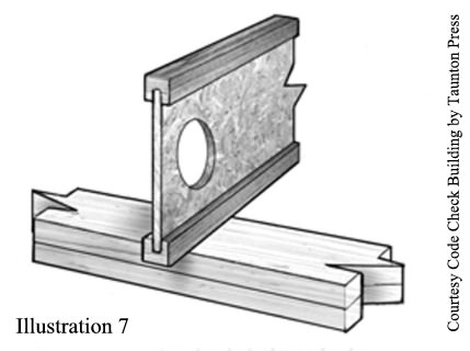
Pre-punched holes up to 1 1/2" are normally placed along the bottom flange and are on 4-foot-centers to facilitate wire runs and plumbing runs. Any holes that must be cut through the web of the joist must be properly placed. The closer to the bearing point of the joist, the smaller the hole diameter allowed. Larger holes must be further from the bearing point (See Illustration 6).
http://www.inspectorsjournal.com/forum/uploads/hausdok/2006613185834_IjoistsIllustration6small.JPGhttp://www.inspectorsjournal.com/forum/uploads/hausdok/2006613185925_IjoistsIllustration7small.jpghttp://www.inspectorsjournal.com/forum/uploads/hausdok/200661319854_IjoistsPhoto2small.jpghttp://www.inspectorsjournal.com/forum/uploads/hausdok/2006613191029_IjoistsPhoto3small.jpg
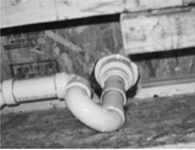
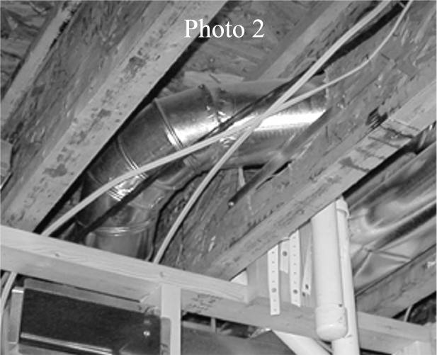
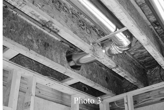
Manufacturers provide specific directions for cutting holes that must be followed. To understand the principles behind the directions, it’s helpful to know the general rule-of-thumb is to multiply the hole diameter by 10 and create the hole that distance from the bearing point. Say a plumber needs to cut a 3" hole through a joist’s web to set a toilet’s waste line. The directions will guide him to cut at least 30" (3 x 10) away from the girder. A 3-inch hole only 12-inches away from the bearing point voids the warranty and will likely need an engineered design repair. (See Illustration 7 and Photos 2 & 3).
COMMON FAULTS
I often find the following faults with the newer flooring systems:
• lacking the necessary fillers,
• missing squash blocks,
• missing web stiffeners,
• damaged or undersized blocking panels,
• out of plumb joists,
• damaged hangers (See Photo 4, above), and
• inappropriate hole placements.
http://www.inspectorsjournal.com/forum/uploads/hausdok/2006613192037_IjoistsPhoto4small.jpgIn addition, I routinely find over-spanned joists where the framers failed to read the details on the plans. wood I-joists can be placed on 12, 16, or 24-inch (all divisible into 48") centers. Be aware that 19.2-inch centers are also allowed because 19.2" can be divided into 96" (48+48=96). Sometimes logic suggests this 19.2-inch center cannot be real. It is, and it can be critical. If the plans call for 19.2-inch centering and the framers set them on 24 inches, it’s a major error.
I recommend having a copy of the information from apawood.org’s Web site on hand during a framing inspection to help explain the errors to the site superintendent. I’ve watched foremen become frustrated trying to use manufacturer’s booklets; however, the graphics and descriptions from this Web site have helped me effectively communicate my concerns.
FEWER FRAMING ERRORS - IMPROVED HOUSING STOCK
My hope is that sharing this information and references for additional information will increase understanding of how building material systems interact, and more specifically it will increase the understanding of point loads relating to the newer flooring systems. Our housing stock will improve if framing errors are corrected prior to being enclosed with drywall and finished floor coverings. I know new homebuyers are willing to pay for inspections by those who have the experience, knowledge, and ability to discover these errors when they can reasonably be corrected. And it’s my experience, homebuyers almost always bring us back for the final inspection of the completed home.
**ABOUT THE AUTHOR: JD Grewell is the owner of J.D. Grewell & Associates, Inc. in Silver Spring, MD. A member of ASHI since 1979, he chairs the Standards of Practice Committee and is active in the MAC-ASHI Chapter. He would like to credit the following individuals and thank them for their technical reviews and suggested editing of this article: Ray Begin, PE; Mike Casey; Bill Coull, PE; Mark Cramer; Bob Fennema, PE; Gerry Loesch, PE; Peter Seirup, PE; and Stuart Zwang, PE. **
[size=2]Hope this helps a little. [/size]
[size=2]Marcel 
[/size]


