This may be difficult to see from the photo, but I will explain clearly what I could and could not determine.
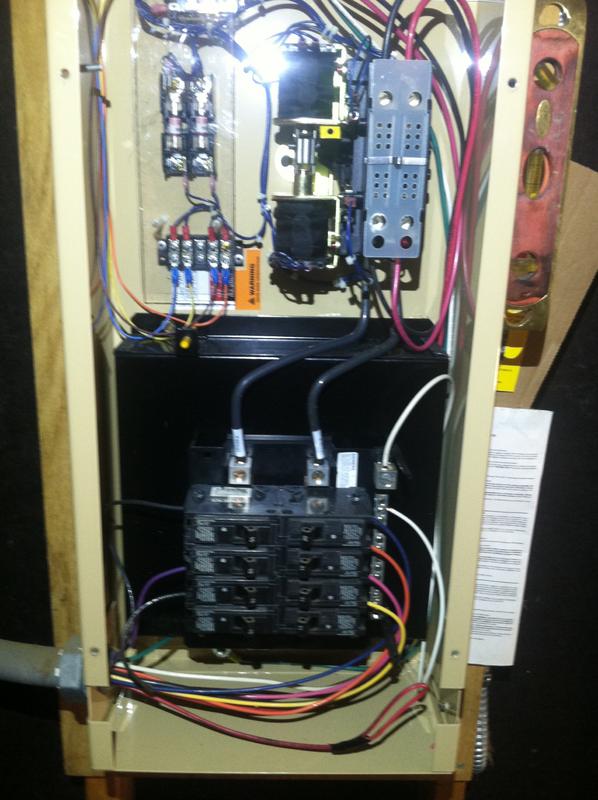
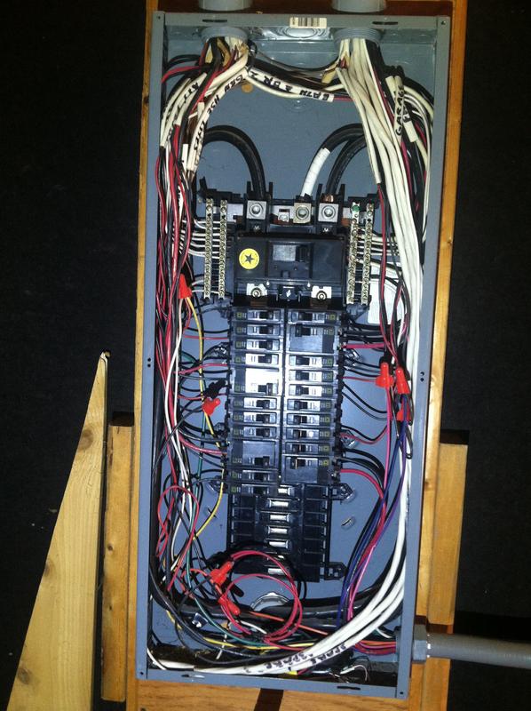
This is a main panel with a Guardian generator transfer panel installed to the side of it. The transfer panel is always sending power to the circuits because those circuits have bypassed the main panel and when an outage occurs the transfer panel changes the source of service.
Nearly all of the circuits in the main panel were originally installed using MWBC all 12-3 w/G. When the transfer panel for generator system was installed, they randomly selected circuits which they wanted to power during an outage. Some of the circuits they moved to the transfer panel are now(I believe) installed on the same phase.
I was able to trace most of the wiring and have marked with matching colored stickers the circuits which share the neutral with the yellow, purple and pink wires in the transfer panel. What I am not 100% certain of is which phase (I have labeled them A & B) goes to which breakers in the transfer panel. I assume they alternate straight down the columns, matching on both sides.
I believe now there are MWBC with shared neutrals installed on the same phase. Am I seeing this correctly?