See photo link below. I was told by an electrician that this heat/resistance can be caused by a loose wire or possible load problem. Does that sound right? Is this something you guys call out and if so, what wording do you use? Thanks.
I have called this type of thing out before, and even had a client get back in touch with me saying how great of a catch it was as the line was loose and almost fell out at the connection. So I’m confused as to how I can determine if/when it’s a problem. So far most folks on this post as saying it’s not an issue.
Geez, if that breaker is 110-115F, in some parts of the country the ambient air would be hotter than the terminal. Yes, it may be hotter than ambient but that doesn’t mean there’s a problem. Most wire today is rated at 90C or about 150F. Many regular breakers are rated to operate in 140F ambient air.
Interesting that the electrician knows more than you do.
Yes, he is correct (but you should know why).
You should never point a TI camera at anything you don’t understand.
In the case of electrical applications, there is a wide assortment of things you can tell from the scan (not just that it is hot).
How did you come up with the emissivity level?
Did you correct for reflected apparent temperature?
How did you do that?
What was the amperage on the circuits?
What was the load correction factor?
As you can see, when you change E the span and temp changes …
out of curoisity what is the manufactures load and operating temp, its usually stamped on the side, thi swill tell you if there is a problem. I see nothing out of the oridanary in the picture to warrent a electrician coming in. Were you able to see where the circut was going and what was drawing from it.
Also as David said what were the other factors, RAT FORD corected temp, also you need to put your spot on the spot you want to measure, this also makes it easier for people to answer questions cuz we have more info. as a side note were you wearing your ppe when you put your camera in the panel.
The heat levels from high emissivity plastics breakers and romex
do not look alarming. Your E setting is close enough for this material.
The PATTERN of heat build up coming coming from the service
wire on the main breaker may be a concern. You would not
normally see the large service wire showing much heat if there is
only one breaker under a normal load.
If there are other breakers loaded, all on one side of the panel,
then your pattern may be normal. If breakers are loaded on both
sides of the panel, then the ONE service wire heating up may indeed
be a load distribution issue or corrosion, as your electrician noted.
An electrician would need to call out the exact defect, after testing.
Sometimes a heat issue will be mild as it moves toward more
heat over time, as the defect continues to degrade. Many panels
have minor distribution issues and people don’t know it. It ends
up using more energy, but does not rise to the level of a safety
concern in many cases. But corrosion at any stage should be corrected.
Some issues can be seen by the PATTERN and some by TEMP.
David’s comments would give us even more precise details.
Thanks John, that’s the kind of info I was looking for. Incidentally, I’m still interested in taking your course one of these days. Hope things are well in Texas.
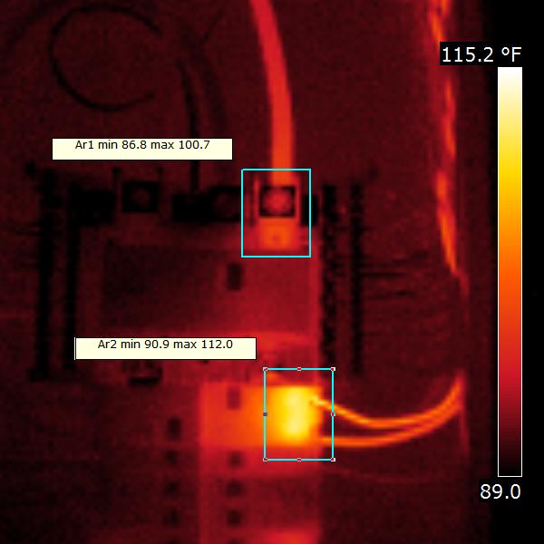
Delta 1 compares the temps of the two legs. If they are under similar loads you can compare to one another (this is not a good assumption here because we don’t know the loading, but we’ll use it for illustration). The Delta between two feeder connections is 5.0C (low end of NETA priority 3)
Delta 2 compares the hotter leg to the ambient temp in the panel using avg of the Ambient labelled box. The Delta between the warmer leg and ambient is 5.1C (NETA priority 4)
Delta 3 compares the warmer breaker to ambient. The Delta between the two is 11.4C (very bottom of NETA priority 3)
As mentioned previously, I don’t see any drama here. None of the temps are anywhere near max rating for components (the “hot” leg is scarcely above body temperature) and the Deltas come out low on the NETA scale. I think the NETA scale is a bit too conservative anyway since they call for investigation at 1C Deltas. I wouldn’t even mention this at all in my report.
I have a different opinion than David. I think you should point you TI at everything you have a chance to and use that as a method to learn how to interpret what you see. However, I don’t recommend you marketing thermography services or reporting observations until you have a lot more experience and knowledge with IR concepts, your imager AND software. Just as buying a point and shoot digital camera and learning how to snap pictures does not make one a professional Photographer, buying a TI and pointing it at stuff does not make one a professional Thermographer.
As for training, I would go for a course that has an accredited certification program.
I love that you use NETA, Chuck. The are various PDM scales like NETA. I highly recommend all of you using some form of standardized scale like this is your reporting. It also takes a lot of guess work out of reporting and image interpretation.
Although some responces in this thread are borderline to just being critical of the OPs question, Chucks responce has brought to light some valuable info for all.
FYI these PDM reference scales are covered in Level II training. Yet another good reason why many here are preaching the training even though some think it is just some way for companies to milk inspectors.
Also… corrosion (or a damaged lug, loose connection, etc…) will usually create a pattern that indicates a localized hot spot is building up, instead of the entire length of the conductor glowing with heat (it is normal, in many cases, to see the entire length of the conductor glowing with heat when under load - up to a certain point).
If the main service wire has a little heat, as above, over the entire length of the conductor, then it will probably be more of a distribution signature, and not a localized corrosion hot spot. We see this many times and it is usually not an issue that rises to the level of a safety item (unless other factors can be introduced). I would leave it to an electrician to actually call out something as a distribution issue that needs repair. With a different set of loads placed on the entire system, then it may not have a distribution issue at all. It is very common to see panels that are a little out of balance.
request that a master electrican check it out. Yes, loose wires can and does make
problems and increases amps thus ups the electrical bill.
alum. wires are very bad about expanding and contracting making a problem breaker panel.
jseffrin
(Jim Seffrin, Director of Infrared Training)
17
Dear Scott:
Welcome to the exciting world of infrared thermography!
Although you do not provide all of the information needed for a detailed analysis, your thermal image is intriguing and noteworthy for the following reason.
The main panel lug on the right exhibits a thermal pattern typical of a defective connection. Notice how heat on the cable is localizalized to the area of the connection and appears to significantly cool within a few inches of the lug.
Assuming that there is not a significant change in the emittance of the cable, this type of thermal pattern is the classic signature of a loose/deteriorated connection. In making such a find, you should be careful in using temperature to qualify the severity of the problem. The operating temperature of loose connections can increase significantly with little or no warning and lead to catastrophic failure of the subject component.
In some cases, a temperature rise of 1 C can be indicative of a significant problem. Because one can never predict time to failure utilizing temperature, this component should be properly investigated for cause as soon as possible and proper corrective measures taken.
Furthermore, when diagnosing exceptions, one should keep in mind that maximum operating temperatures are provided for devices operating at 100% load and a specified ambient air temperature. For devices operating at less than full load and/or ambient temperatures other than those specified, it is possible to apply a formula known as TmaxCorrected.
In order to apply the TmaxCorrected formula you will need some additional information including circuit load, ambient air temperature, and an ***accurate ***operating temperature of the subject component. Although it takes a little more time to perform than a qualitative observation or an apparent Delta T calculation, this formula will enable you to ascertain whether a component is operating within spec for any given load or ambient temperature. Your double pole breaker would be a good candidate for applying this formula.
Proper use of the TmaxCorrected formula and several temperature severity guides, including NETA, can be found within the Standard for Infrared Inspection of Electrical Systems and Rotating Equipment](http://www.infraspection.com/useful_guidelines.html#1). This comprehensive 17 page document also outlines practices and procedures for safely performing infrared inspections of operating electrical systems. Copies are available from the Standards Section of Infraspection Online Store.
If you are interested in truly unlocking the potential of your infrared imager ($200,000 per year) and being capable of confidently diagnosing your imagery, I would suggest you take both a Level I and Level II training course where the above topics are covered in detail along with several other applications. Both courses are available as open enrollment classes or via our Distance Learning Program.
Please feel free to give me a call should you have any questions or if we can be of further assistance.