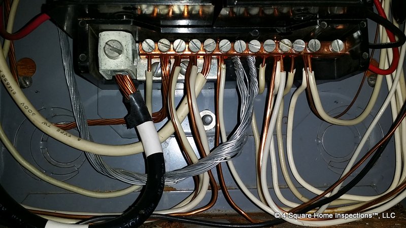
This looks like a split bus panel. There is no main breaker (the top breaker is a 50 amp lighting breaker). The secondary panel (left) is double lugged from the primary (no over-current protection). The secondary has an improper bond with the equipment ground and neutral even though there theoretically does not carry any current (220). There are several double tapped neutral conductors both with equipment grounds and other neutrals. Any suggestions on how to write this one up?


Is there a safety switch before the panel? If there is it would explain no main breaker if not put the covers back on write it up as immediate repair is required by Licenced Electrical Contractor there are many safety issues.
No there wasn’t just the meter socket. I did write it up. I’ve never seen this design before.
You are permitted to have up to 6 service disconnects. The lack of a singular main is not a problem.
The problem I had with the panel is it was unclear as to how many of the “top breakers” on the lower half of the panel were independent of the 50 amp breaker on the top. In any case, there were more than the rule of 6 would permit in my opinion.
Looks like that top breaker supplies power to the entire bottom.
But the main lugs are in the middle. Top breaker is only 50 amps.
Hahaha I just looked again.
Looks like the service comes in and attaches to those lugs in the middle. The bus actually supplies power to breaker up top. The lugs are double tapped to feed the sub panel. The grounded and grounding conductors are bonded in the sub panel.
Lol I think you should just recommend an electrician. It’s all FUBAR
Look at the diagram from the panel cover. The SEC’s (connected at the A and B triangles) are feeding 3 CB’s, the top one and the two below it. The load side of the left “lighting main breaker” feeds the bottom portion of the panel.
Robert it looks like the SEC’s bypass the breaker and attach right to the lugs.
My mistake, the diagram and the photo do not match. It’s the top CB that feeding the lower portion of the panel, the area below the two CB’s under the main lugs. If you follow the two conductors leaving the left side of the top CB you can see they disappear behing the other CB’s. These are attached to the lower section of bus as depicted in the panel diagram.
A bit messy to say exactly whats happening but a lot does stand out. Not a typical design for a split but it has violations:(.
Thebiggest concern in all this is what looks like the main service neutral conductor is pulled out of the neutral buss lug. If so at this point either the water bond is picking up the neutral load or the loads are in series. Both dangerous conditions and the latter is a fire concern that needs to be addressed immediately. I really recommend instructing the property owner to immediately call an electrician over. Classic open neutral case.
Now for the violations. The main service conductors run straight into the lighting section hence the 6 throw rule is in violation. Also the lugs are double tapped and not listed for such. And as you mention a neutral to ground bond in the sub panel. The main panel (although Im not to familiar with early vintage panels) may not be bonded. Normally a strap is present from the neutral buss to the tub, although in this case the silver screws may or may not be doing it.
I would list it much like I did. However once the open neutral condition is mentioned any electrician will fly right over.
My 2 cents