New Build Roof Framing

There are 2 types of gypsum board. Regular Type X below the ledger, and a different type of Type X behind and above the ledger with a brown paper on the face instead of white. They used the same type in the attic space. Why? I don’t know. There is Blue gypsum board in the middle of the common wall, also fire rated.

As @lkage pointed out it is 5/8" doubled up on this side of the wall. So technically 1 1/4" thick.

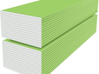
Robert, this is a common, or “shared” wall in a duplex townhome. The framing method is two 2X4 walls with a space between them for Gypsum board. Similar to this diagram:

There are about a dozen of these duplexes all built on the same street, in the same manner, with nearly identical floor plans. The design of each is almost reminiscent of the old “shotgun” style home in the southern U.S.

The funny thing is, in the garages, they didn’t put the Blue gypsum board in the wall cavity like they did for the living space areas, even though the walls line up on the foundation. For the garages, they put a single layer of regular Type X drywall on either side of the walls and a doubled up layer of the brown papered “fire board” sandwiched between the trusses above the wall. I only know this, because I was on location pouring concrete when several of these townhomes were being framed and watched the framers do this. I very well could have watched this home being framed without realizing it. We didn’t have actual addresses to go by when the foundations were going in, just a street and subdivision name, LOL.

Except these are not just ceiling joists, they are roof trusses. Personally, I would rather see them sitting on hangers rather than a ledger like this.

I don’t have the load designs or specs for these trusses, nor am I going out of my way to find them. That’s an SEs job. I couldn’t even tell you how the tops of the trusses were fastened to the wall or other trusses. I couldn’t see any nails. They could have been toe nailed through the truss plate or have blind nails through the back. This area is a typical gable style roof design with a split 2X4 wall sitting on the foundation. There is a possibility the trusses on the other side of the wall were resting on top of the wall I suppose. I tried to see if anyone was home next door when I did the inspection so I could take a peak at the other side, but no body was there unfortunately.

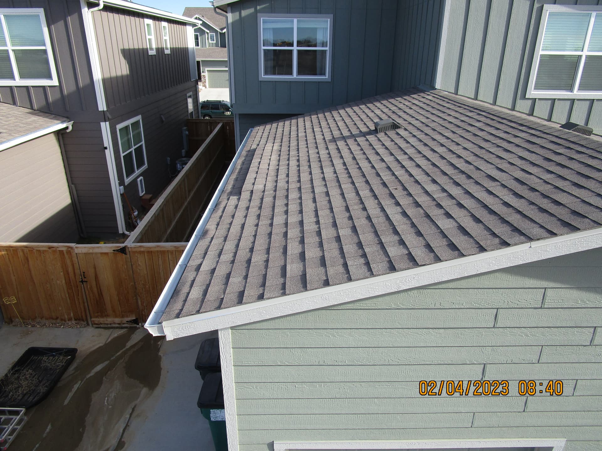
Here is a picture of the roof in the area for perspective.

That’s right. my numbers from last night were incorrect. I’m too used to dealing with duplex nails where you don’t measure from the striking portion of the head like you do a box or common nail. Old habits… :roll_eyes: hehehe…

1 Like

Minimum bearing for joists is 1.5 inches or an approved hanger. So a 1x is too narrow. (It looks like the 1x is nailed to the beam).I believe they want that notch filled in but you’ll have to look at the truss layout to be sure. I have seen trusses like that that did not require a hanger because it’s bearing on a wall etc. at the notch. Again it pays to look at the truss layout if it’s laying around. I think it’s poor practice not to fill the notch in. The truss company generally supplies the hangers so if there’s half a box of hangers laying around…then they might have missed some.

Be it a ceiling joist or bottom chord, 1.5" inches is sufficient width for point load.
I doubt the ledger is 1.5" inches.
It’s wrong. Structural Engineer required to further evaluate and made necessary changes.

Are you sure about that? Doesn’t look like it to me over in this area.

1 Like

If you look at the 2x at the wall, there is 1.5 inches of bearing on that ledger. Biggest issue there is the attachment of the ledger board. Appears only nailed. The truss design is correct. I spoke with a former truss designer and building official regarding all that. Proper attachment of the ledger should be the only issue there.

1 Like

Morning, Gregory.
Hope this post finds you well.

Am I to take it the ledger is 1.5" thick? As well, the mono pitch roof truss end brace is likely 2" inches with only 50% bearing on the ledger.
The ledger might be 1.5" thick but from my angle it looks like a 1" by 10".

I’d wager the ledger is 1.5. Drywall below is covering some of the edge.

Very common in commercial structures, often used for elevators shafts ect.

Call the local building department and ask for the building Plans.

1 Like

My mistake. Sorry.

Nothing to be sorry about. It’s a matter of perspective and angle. Easy to assume

Kind of you for saying…
Greg, actually I should have realized the ledger was 2" thick from the get go. Absolutely dumb to think otherwise…

Yep.
1 in. (25.4 mm) glass-mat Type X liner panels with moisture and mold resistance for use in shaft wall and area separation wall systems

image

4 Likes

You’d win that wager. The ledger was a 2x8.

@ryoung7 the section on the right in the “standing further back” picture had a rolled bark edge on the bottom, making it look like a 1X. I tried to get a close up picture of it but my attempts were useless and out of focus. There was a car in there with a dead battery against that wall, and it couldn’t be moved, making taking pictures difficult to say the least.

1 Like

I’m a little surprised that the “fire proofing” drywall wasn’t extended to the roof deck.

I built a few fourplexes just prior to covid and not only did the firewall need to extend to the roof deck but 4’ on each side of the common walls the sheeting needed to treated with fire retarding coatings. And we had to install a layer of Sheetrock between the trusses.

1 Like

Here’s a pile that is blue from a Townhouse project I was on yesterday.

It comes in a bunch of colors with different ratings for fire, moisture, mold, permeability, etc… Was on a school project a few months ago that had yellow w fiberglass on one side They were using it on exterior walls and setting brick in front of it. Wish I had some pictures… It too was 1" thick. Installers had special blades on their saws for cutting it so they didn’t mess up the fiberglass.

The best advice is to recommend the builder, framer, AHJ and/or architect revisit the installation if it looks/seems incorrect.

That being said, as a learning tool, remember there is a horizontal component of the load on that roof. I still remember (and am tortured by) “free-body-diagrams” from college physics. As the load is applied to that roof there is a vertical AND horizontal force vector (it’s been 25+ years, hopefully I’m using “vector” properly).

The horizontal component helps in holding that connection so it’s not just a strictly vertical/shear load being applied to those nails (think setting a 2X4 against the wall and barely holing vs. pushing it into the wall hard). As Brian calculated, 3/4" of penetration is terrible and should be revisited but, depending on the slope of the roof, the actual load on the nails might be less than you think.